
| Version 46 (modified by gah, 11 years ago) (diff) |
|---|
Synopsis
A mesh defines the vertices in 2D or 3D for a set of values of a <field> element. The <mesh> describes where each value of the <field> is found. A mesh contains mesh elements that indicate their connectivity (topology) and geometry.
There are three basic formats for meshes, given by the subelements <grid>, <unstructured>, and <vtk>. It is an error to have more than one in a <mesh> definition.
- <grid>
- Defines a structured grid such as a rectangular or curvilinear grid. Structured grids have a very compact representation. Cells and points are indexed by i,j,k of grid lines. Grid lines run through the entire domain. For example, volume rendering requires a uniform rectangular grid.
- <unstructured>
- Defines an unstructured grid that is composed of cells: triangles, quads, tetrahedrons, hexahedrons, wedges, pyramids, etc. The cells can be all one type like triangles, or mixed. Cells can be arbitrarily positioned. Grid lines do not have to run through the entire domain (there can be holes).
- <vtk>
- Uses the VTK legacy file format to describe the mesh.
Pick the one that most closely resembles the structure of your data set.
How to specify meshes
    <mesh>
        <about>
             <label>3D Mesh</label>
        </about>
        <dim>3</dim>
        <units>um</units>
        <hide>yes</hide>
        ...
    </mesh>
All meshes should have <dim>, <units> and <hide> subelements.
- <dim>
- This defines the dimensionality of the mesh. It should be either "2" or "3". It is an error if this is missing from the mesh definition.
- <units>
- This is the units for the X, Y, and Z coordinates of the mesh. If one units name is present, then all axes use the same units. Otherwise you can specify a units name for each axis.
- <hide>
- This value should be "yes" or "no". This says if the mesh should be displayed as an output. Typically this should be "no".
- <about><label>
- This is the label for the mesh. It's used to label the output if the mesh isn't hidden.
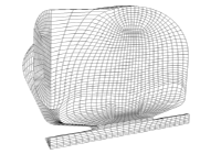
Structured Grids
A <grid> element describes a structured grid. Structured grids include rectangular grids, non-uniform rectilinear grid, and curvilinear grid.
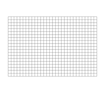
Uniform Rectangular Grid


In a uniform rectangular grid the grid lines run along each axis. You specify the minimum and maximum values, and the number of grid lines for each axis. For 2D grids you specify the X and Y axes. For 3D grids you specify the X, Y, and Z axes.
The subelements <xaxis>, <yaxis>, and <zaxis> are used to describe each axis.
- <xaxis><min>
- Minimum value for the X-axis.
- <xaxis><max>
- Maximum value for the X-axis.
- <xaxis><numpoints>
- Number points on the X-axis, including the minimum and maximum values.
- <yaxis><min>
- Minimum value for the Y-axis.
- <yaxis><max>
- Maximum value for the Y-axis.
- <yaxis><numpoints>
- Number points on the Y-axis, including the minimum and maximum values.
- <zaxis><min>
- Minimum value for the Z-axis. This is needed only for 3D grids.
- <zaxis><max>
- Maximum value for the Z-axis. This is needed only for 3D grids.
- <zaxis><numpoints>
- Number points on the Z-axis, including the minimum and maximum values. This is needed only for 3D grids.
    <mesh>
        <units>m</units>
        <hide>yes</hide>
        <dim>2</dim>
        <grid>
            <xaxis>
                <min>0.0</min>
                <max>1.0</max>
                <numpoints>50</numpoints>
            </xaxis>
            <yaxis>
                <min>0.0</min>
                <max>1.0</max>
                <numpoints>50</numpoints>
            </yaxis>
        </grid>
    </mesh>
Both the X and Y axes of the mesh contain 50 points, evenly spaced between 0.0 and 1.0. The <min>, <max>, and <numpoints> subelements define the the minimum axis position, the maximum axis position, and the number of uniform points between them (including the minimum and maximum).
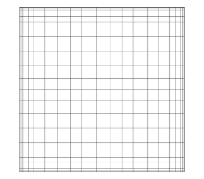
Non-uniform Rectilinear Grid


Another form of a structured grid is a non-uniform or irregular rectilinear grid. You specify the points on each axis using the <xcoords>, <ycoords>, and <zcoords> subelements.
- <xcoords>
- A list all the coordinates on the X-axis. The coordinates do not have to be uniformly spaced.
- <ycoords>
- A list all the coordinates on the Y-axis. The coordinates do not have to be uniformly spaced.
- <zcoords>
- A list all the coordinates on the Z-axis. The coordinates do not have to be uniformly spaced.
Here is an example of an irregular rectilinear 2D grid.
    <mesh>
        <units>m</units>
        <hide>yes</hide>
        <dim>2</dim>
        <grid>
            <xcoords>
                0.0 0.0204081632653
                0.0408163265306 0.0612244897959 0.0816326530612 0.102040816327
                0.122448979592 0.142857142857 0.163265306122
                ...
                0.836734693878 0.857142857143 0.877551020408 0.897959183673
                0.918367346939 0.938775510204 0.959183673469
                0.979591836735 1.0
            </xcoords>
            <ycoords>
                0.0 0.0204081632653 0.0408163265306 0.0612244897959
                0.0816326530612 0.102040816327
                ...
                0.836734693878 0.857142857143 0.877551020408
                0.897959183673 0.918367346939 0.938775510204
                0.959183673469
                0.979591836735 1.0
            </ycoords>
        </grid>
    </mesh>
This is the same mesh as the uniform 2D grid example above except that we specify each point along the X and Y axes in <xcoords> and <ycoords> elements.
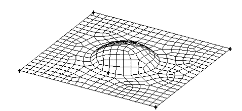
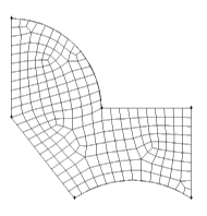
Curvilinear Grid

In a curvilinear grid you specify to locations of each point in the grid. The grid lines do not need to be aligned to any axis.
The number of points is determined by the <xdim>, <ydim>, and <zdim> values (numberOfPoints = xdim * ydim * zdim).
- <xdim> The number of coordinates along the X-axis.
- <ydim> The number of coordinates along the Y-axis.
- <zdim> The number of coordinates along the Z-axis. This is needed only for 3D
- <points> This is a list of points that represent the mesh. The points do not need to be aligned. If this is a 2D grid, then every 2 numbers represent a point in the mesh. In a 3D grid, every 3 numbers represent a point in the mesh. The number of points is determined by the '<xdim>, <ydim>, and <zdim> values.
    <mesh>
        <units>m</units>
        <hide>yes</hide>
        <dim>3</dim>
        <grid>
           <xdim>20</xdim>
            <ydim>30</ydim>
            <zdim>40</ydim>
                3.90799e-16 9.85395e-06 0.00041631
                0.00176643 0.00364602 0.0259133
                0.000922976 0.00487217 0.0552675
                0.00454433 0.00233178 0.0833129
                0.00931732 0.0056806 0.105561
                0.000508319 0.00767051 0.125189
                ...
            </points>
         </grid>
    </mesh>
You can mix uniform and non-uniform axes. Below is an example of a 2D grid where the X axis is uniform and the Y-axis is non-uniform.
    <mesh>
        <units>m</units>
        <hide>yes</hide>
        <grid>
            <xaxis>
                <min>0.0</min>
                <max>1.0</max>
                <numpoints>50</numpoints>
            </xaxis>
            <ycoords>
                0.0 0.0204081632653 0.0408163265306 0.0612244897959
                0.0816326530612 0.102040816327
                ...
                0.836734693878 0.857142857143 0.877551020408
                0.897959183673 0.918367346939 0.938775510204
                0.959183673469
                0.979591836735 1.0
            </ycoords>
        </grid>
    </mesh>
Unstructured Grids
Unstructured grids are composed of cells: hexahedrons, wedges, pyramids, etc. The cells can be all one type like triangles, or mixed. Cells can be arbitrarily positioned. Grid lines do not have to run through the entire domain (there can be holes). All unstructured grids use <points> to specify the vertices of the cells.
- <points>
- These are the points of all the vertices. Each line should contain two or three numbers, depending upon the dimensionality of the mesh.
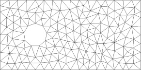
Triangles

A <triangles> subelement in an unstructured grid describing a triangular grid consisting of all triangle cells. It contains a <points> subelement that defines all the vertices used by the triangles. The <triangles> subelement defines the indices of each vertex (numbered from zero) that make up each triangle. Every three indices describe a triangle.
    <mesh>
        <units>m</units>
        <hide>yes</hide>
        <dim>2</dim>
        <unstructured>
            <points>
                0.0 0.0
                0.02040816326530612 0.0
                0.04081632653061224 0.0
                0.061224489795918366 0.0
                0.08163265306122448 0.0
                0.1020408163265306 0.0
                0.12244897959183673 0.0
                0.14285714285714285 0.0
                ...
            </points>
            <triangles>
                93 44 43
                98 49 48
                19 70 20
                25 76 26
                29 80 30
                34 85 35
                ...
            </triangles>
        </unstructured>
    </mesh>
- <points>
- These are the points of all the vertices. Each line should contain two numbers representing the X and Y cooridinates of he point.
- <triangles>
- This is the list of indices for each triangle. The indices are numbered from zero and indicate the index of the point in <points>. There are 3 indices per triangle.
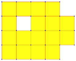
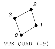
Quads

A <quads> subelement in an unstructured grid describing a grid consisting of all quadrilateral cells. It contains a <points> subelement that defines all the vertices used by the triangles. The <quads> subelement defines the indices of each vertex (numbered from zero) that make up each quadrilateral. Every four indices describe a quadrilateral cell.
    <mesh>
        <units>m</units>
        <hide>yes</hide>
        <dim>2</dim>
        <unstructured>
            <points>
                0.0 0.0
                0.02040816326530612 0.0
                0.04081632653061224 0.0
                0.061224489795918366 0.0
                0.08163265306122448 0.0
                0.1020408163265306 0.0
                0.12244897959183673 0.0
                0.14285714285714285 0.0
                ...
            </points>
            <quads>
                93 44 43
                98 49 48
                19 70 20
                25 76 26
                29 80 30
                34 85 35
                ...
            </quads>
        </unstructured>
    </mesh>
- <points>
- These are the points of all the vertices. Each line should contain two numbers in 2D, or three numbers in 3D, representing cooridinates of the point.
- <quads>
- This is the list of indices for each quadrilateral cell. The indices are numbered from zero and indicate the index of the point in <points>. There are 4 indices per quadrilateral cell.
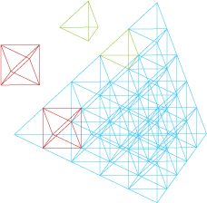
Tetrahedrons

A <tetrahedrons> subelement in an unstructured grid describing a grid consisting of all tetrahedral cells. It contains a <points> subelement that defines all the vertices used by the tetrahedrons. The <tetrahedrons> subelement defines the indices of each vertex (numbered from zero) that make up each tetrahederon. Every four indices describe a tetrahedron.
    <mesh>
        <units>m</units>
        <hide>yes</hide>
        <dim>2</dim>
        <unstructured>
            <points>
                0.0 0.0
                0.02040816326530612 0.0
                0.04081632653061224 0.0
                0.061224489795918366 0.0
                0.08163265306122448 0.0
                0.1020408163265306 0.0
                0.12244897959183673 0.0
                0.14285714285714285 0.0
                ...
            </points>
            <tetrahedrons>
                93 44 43
                98 49 48
                19 70 20
                25 76 26
                29 80 30
                34 85 35
                ...
            </tetrahedrons>
        </unstructured>
    </mesh>
- <points>
- These are the points of all the vertices. Each line should contain two numbers representing the X and Y cooridinates of he point.
- <tetrahedrons>
- This is the list of indices for each tetrahedron. The indices are numbered from zero and indicate the index of the point in <points>. There are 4 indices per tetrahedron.
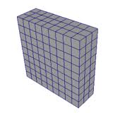
Hexahedrons
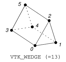
Wedges
Pyramids
Cells
Point Clouds
Hybrid Cells
An <unstructured> element describes a mesh of cell types. Each cell has a VTK cell ID listed below.
Vertex 1 Poly Vertex 2 Line 3 Poly Line 4 Triangle 5 Triangle Strip 6 Polygon 7 Pixel 8 Quad 9 Tetra 10 Voxel 11 Hexahedron 12 Wedge 13 Pyramid 14 Pentagonal Prism 15 Hexagonal Prism 16
- <points>
- These are the points of all the vertices. Each line should contain two or three numbers, depending upon the dimensionality of the mesh.
- <cells>
- These are the cells in the mesh, one cell per line. Each cell contains the number of indices for that cell along with the indices themselves. The indices are numbered from zero and indicate the index of the point in <points>.
- <celltypes>
- These are the cell types in the mesh, one for each cell. The cell types is the numeric VTK id for the cell.
    <mesh>
        <units>m</units>
        <hide>yes</hide>
        <dim>2</dim>
        <unstructured>
            <points>
                0.0 0.0
                0.0204082 0.0
                0.0408163 0.0
                0.0612245 0.0
                ...
            </points>
            <cells>
                5: 93 44 43
                5: 98 49 48
                9: 19 70 20 26
                14: 25 76 26 81 109
                ...
            </cells>
        </unstructured>
    </mesh>
Note that you can specify something like the deprecated <cloud> mesh by defining an unstructured mesh with only points, as follows:
    <mesh>
        <units>m</units>
        <hide>yes</hide>
        <dim>2</dim>
        <unstructured>
            <points>
                0.0 0.0
                0.0204082 0.0
                0.0408163 0.0
                0.0612245 0.0
                ...
            </points>
        </unstructured>
    </mesh>
Since there are no cells in this mesh, the mesh will be generated automatically by Rappture as a set of triangles (2D) or tetrahedra (3D).
Note that you can specify a triangular mesh as follows:
    <mesh>
        <units>m</units>
        <hide>yes</hide>
        <dim>2</dim>
        <unstructured>
            <points>
                0.0 0.0
                0.0204082 0.0
                0.0408163 0.0
                0.0612245 0.0
                ...
            </points>
            <cells type="5">
                93 44 43
                98 49 48
                19 70 20
                25 76 26
                ...
            </cells>
        </unstructured>
    </mesh>
The argument type=5 for the <cells> tag indicates that all elements should be triangles (3 point indices).
VTK Legacy File Format
A <vtk> element uses the VTK legacy file format to describe the mesh. The advantage of describing the mesh in VTK file format is that you can have heterogeneous cell types.
The <vtk> element contains only a part of a VTK file. It consists of
- a DATASET keyword and the dataset type (STRUCTURED_POINTS, STRUCTURED_GRID, UNSTRUCTUTRED_GRID, POLYDATA, or RECTILINEAR_GRID) and
- the dataset definition itself.
POINT_DATA and CELL_DATA are not included. They will be added by the <field> that is using this mesh.
    <mesh>
        <units>m</units>
        <hide>yes</hide>
        <dim>2</dim>
        <vtk>DATASET UNSTRUCTURED_GRID
POINTS 2500 float
    0.0 0.0 0
    0.0204082 0.0 0
    0.0408163 0.0 0
    0.0612245 0.0 0
    0.0816327 0.0 0
    0.102041 0.0 0
    ...
CELLS 4802 19208
    3 93 44 43
    3 98 49 48
    3 19 70 20
    3 25 76 26
    3 29 80 30
    3 34 85 35
    ...
CELL_TYPES 4802
    5
    5
    5
    5
    5
    5
    ...
        </vtk>
    </mesh>
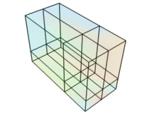
Old Mesh Format
There is a general form of a <mesh> that lets you the specify each element and explicitly describe their connectivity.
    <mesh>
        <about>
            <label>3D Mesh</label>
        </about>
        <units>um</units>
        <hide>yes</hide>
        <<node id="0">0 0 0</node>
        <node id="1">1 0 0</node>
        <node id="2">2 0 0</node>
        <node id="3">3 0 0</node>
        ...
        <element id="0">
            <nodes>0 1 5 6 25 26 30 31</nodes>
        </element>
        <element id="1">
            <nodes>1 2 6 7 26 27 31 32</nodes>
        </element>
        ...
    </mesh>
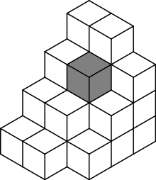
In the general form a <mesh>, you can explicitly define a set of points and their connectivity. Each point is defined as a <node> with a specific id. In this example, we have a 3D mesh, so each <node> contains an (x,y,z) coordinate. The mesh also contains a series of <element> objects, which indicate how the nodes are stitched together to form a mesh. The first element is a cube composed of nodes with identifiers (id=) 0, 1, 5, 6, 25, 26, 30, and 31. Note that this mesh has a hole in the center. There is no element defined that connects the inner nodes. This is not an error. It represents a hole in the underlying structure.
Each value in the field corresponds to a node in the mesh. The first value represents the field at the first node (id=0), the next value at the next node (id=1), and so forth.
- <node>
- These are the points of the mesh. Each <node> subelement contains the x y and z coordinates of a point. The "id" is important. It is used by <element> subelements to stitch together points to form a cell element.
- <element>
- These are the cells of the mesh. Each <element> contains the node ids of the points that compose the cell.
Note: This format is deprecated in favor of the compact mesh types described below. If you need heterogenous cell types, use the VTK file format.
Attachments (22)
- 400px-ParaView_UG_Image.png (24.3 KB) - added by gah 11 years ago.
- 400px-ParaView_UG_Rectilinear.png (16.5 KB) - added by gah 11 years ago.
- triangular_grid.jpg (28.6 KB) - added by gah 11 years ago.
- 220px-Voxels.svg.png (12.1 KB) - added by gah 11 years ago.
- TetrahedralGridColored.jpg (52.9 KB) - added by gah 11 years ago.
- quad_mesh_250x200.png (1.5 KB) - added by gah 11 years ago.
- uniform_rectlinear_mesh.jpg (4.1 KB) - added by gah 11 years ago.
- rectilinear_grid1.jpg (20.8 KB) - added by gah 11 years ago.
- uniform_rectilinear_grid_2d.png (214 bytes) - added by gah 11 years ago.
- 200px-Meshes_Curvilinear_StructuredGrid.png (24.9 KB) - added by gah 11 years ago.
- quad3d.png (14.1 KB) - added by gah 11 years ago.
- quad2d.png (8.7 KB) - added by gah 11 years ago.
- rectilinear2d.png (6.1 KB) - added by gah 11 years ago.
- rectilinear3d.png (28.4 KB) - added by gah 11 years ago.
- hexgrid.png (6.9 KB) - added by gah 11 years ago.
- hexgrid2.png (25.0 KB) - added by gah 11 years ago.
- vtkhexa.png (10.0 KB) - added by gah 11 years ago.
- vtktetra.png (7.0 KB) - added by gah 11 years ago.
- vtkpyramid.png (8.4 KB) - added by gah 11 years ago.
- vtkwedge.png (8.6 KB) - added by gah 11 years ago.
- vtktriangle.png (5.3 KB) - added by gah 11 years ago.
- vtkquad.png (5.5 KB) - added by gah 11 years ago.
Download all attachments as: .zip