
| Version 5 (modified by gah, 11 years ago) (diff) |
|---|
<mesh>
A mesh defines the vertices in 2D or 3D for a set of values of a <field> element. The <mesh> describes where each value of the <field> is found. A mesh contains mesh elements that indicate their connectivity (topology) and geometry.
<mesh id="m0">
  <about>
    <label>3D Mesh</label>
  </about>
  <units>um</units>
  <hide>yes</hide>
   ...
</mesh>
All meshes should have <units> and <hide> subelements.
<units>
This is the units for the X, Y, and Z coordinates of the mesh. If one units name is present, then all axes use the same units. Otherwise you can specify a units name for each axis.
<hide>
This value should be "yes" or "no". This says if the mesh should be displayed as an output. Typically this should be "no".
How to specify meshes.
General Mesh Definition
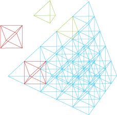
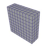
There is a general form of a <mesh> that lets you the specify each element and explicitly describe their connectivity.
<mesh id="m3d">
  <about>
    <label>3D Mesh</label>
  </about>
  <units>um</units>
  <hide>yes</hide>
  <node id="0">0 0 0</node>
  <node id="1">1 0 0</node>
  <node id="2">2 0 0</node>
  <node id="3">3 0 0</node>
  ...
  <element id="0">
    <nodes>0 1 5 6 25 26 30 31</nodes>
  </element>
  <element id="1">
    <nodes>1 2 6 7 26 27 31 32</nodes>
  </element>
  ...
</mesh>


    <values>0
0
0
0
...
    </values>
  </component>
</field>
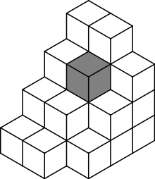
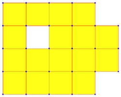
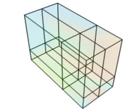
In the general form a <mesh>, you can explicitly define a set of points and their connectivity. Each point is defined as a <node> with a specific id. In this example, we have a 3D mesh, so each <node> contains an (x,y,z) coordinate. The mesh also contains a series of <element> objects, which indicate how the nodes are stitched together to form a mesh. The first element is a cube composed of nodes with identifiers (id=) 0, 1, 5, 6, 25, 26, 30, and 31. Note that this mesh has a hole in the center. There is no element defined that connects the inner nodes. This is not an error. It represents a hole in the underlying structure.
Each value in the field corresponds to a node in the mesh. The first value represents the field at the first node (id=0), the next value at the next node (id=1), and so forth.
There are also more compact subelements for specific types of mesh elements.
Compact Mesh Definitions
There are also more compact descriptions of meshes, where all mesh elements are the same. The subelements <cloud>, <grid>, and <triangles> below describe specific types of mesh elements.
<cloud>
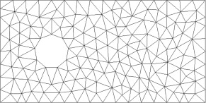
The simplest mesh is a <cloud>. A cloud contains no explicit connectivity. It is implicitly converted into triangular mesh in 2D or a tetrahedral mesh in 3D. The <points> subelement indicates where the individual points are located in the cloud. Each line of <points> specifies a point in the cloud. The dimensionality of the mesh is determined by the number of coordinates on each line: two numbers for 2D, three for 3D. The following is an example of a 2D cloud.
    <mesh id="m1">
        <units>m</units>
        <cloud>
            <points>
               0.0 0.0
               0.0204081632653 0.0
               0.0408163265306 0.0
               0.0612244897959 0.0
               ...
               0.918367346939 1.0
               0.938775510204 1.0
               0.959183673469 1.0
               0.979591836735 1.0
               1.0 1.0
             </points>
        </cloud>
    </mesh>
<grid>
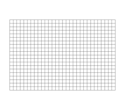
A <grid> element describes a rectilinear mesh on 2 or 3 axes. The axes may be uniform of non-uniform (irregular). The dimensionality of the grid is determined by the axes described. For a uniform grid the subelements <xaxis>, <yaxis>, and <zaxis> can be used to describe an axis. Below is an example of two dimensional uniform grid.
    <mesh id="m2">
        <units>m</units>
        <hide>yes</hide>
        <grid>
            <xaxis>
                <min>0.0</min>
                <max>1.0</max>
                <numpoints>50</numpoints>
            </xaxis>
            <yaxis>
                <min>0.0</min>
                <max>1.0</max>
                <numpoints>50</numpoints>
            </yaxis>
        </grid>
    </mesh>
Both the X and Y axes of the mesh contain 50 points, evenly spaced between 0.0 and 1.0. The <min>, <max>, and <numpoints> subelements define the the minimum axis position, the maximum axis position, and the number of uniform points between them (including the minimum and maximum).
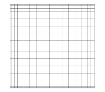
For an non-uniform or irregular axis, you specify the points on the axis themselves using the <xvalues>, <yvalues>, and <zvalues> subelements. Here is an example of a irregular 2D grid.
    <mesh id="m4">
        <units>m</units>
        <hide>yes</hide>
        <grid>
            <xvalues>
                0.0 0.0204081632653
                0.0408163265306 0.0612244897959 0.0816326530612 0.102040816327
                0.122448979592 0.142857142857 0.163265306122
                ...
                0.836734693878 0.857142857143 0.877551020408 0.897959183673
                0.918367346939 0.938775510204 0.959183673469
                0.979591836735 1.0
            </xvalues>
            <yvalues>
                0.0 0.0204081632653 0.0408163265306 0.0612244897959
                0.0816326530612 0.102040816327
                ...
                0.836734693878 0.857142857143 0.877551020408
                0.897959183673 0.918367346939 0.938775510204
                0.959183673469
                0.979591836735 1.0
            </yvalues>
        </grid>
    </mesh>
This is the same mesh as the uniform 2D grid example above except that we specify each point along the X and Y axes in <xvalues> and <yvalues> elements.
You can mix uniform and non-uniform axes. Below is an example of a 2D grid where the X axis is uniform and the Y-axis is non-uniform.
    <mesh id="m5">
        <units>m</units>
        <hide>yes</hide>
        <grid>
            <xaxis>
                <min>0.0</min>
                <max>1.0</max>
                <numpoints>50</numpoints>
            </xaxis>
            <yvalues>
                0.0 0.0204081632653 0.0408163265306 0.0612244897959
                0.0816326530612 0.102040816327
                ...
                0.836734693878 0.857142857143 0.877551020408
                0.897959183673 0.918367346939 0.938775510204
                0.959183673469
                0.979591836735 1.0
            </yvalues>
        </grid>
    </mesh>
<triangles>
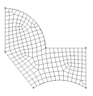
A <triangles> element describes a 2D mesh consisting of a set of triangles. It contains a <points> subelement that defines all the vertices used by the triangles. The <indices> subelement defines the indices of each vertex (numbered from zero) that make up each triangle. Every three indices describe a triangle.
    <mesh id="m5">
        <units>m</units>
        <triangles>
            <points>
                0.0 0.0
                0.02040816326530612 0.0
                0.04081632653061224 0.0
                0.061224489795918366 0.0
                0.08163265306122448 0.0
                0.1020408163265306 0.0
                0.12244897959183673 0.0
                0.14285714285714285 0.0
                ...
            </points>
            <indices>
                93 44 43
                98 49 48
                19 70 20
                25 76 26
                29 80 30
                34 85 35
                ...
            </indices>
        </triangles>
But a <mesh> element defines a set of points and their connectivity. Each point is defined as a <node> with a specific id. In this example, we have a 3D mesh, so each <node> contains an (x,y,z) coordinate. The mesh also contains a series of <element> objects, which indicate how the nodes are stitched together to form a mesh. The first element is a cube composed of nodes with identifiers (id=) 0, 1, 5, 6, 25, 26, 30, and 31. Note that this mesh has a hole in the center. There is no element defined that connects the inner nodes. This is not an error. It represents a hole in the underlying structure.
<cells>
Attachments (22)
- 400px-ParaView_UG_Image.png (24.3 KB) - added by gah 11 years ago.
- 400px-ParaView_UG_Rectilinear.png (16.5 KB) - added by gah 11 years ago.
- triangular_grid.jpg (28.6 KB) - added by gah 11 years ago.
- 220px-Voxels.svg.png (12.1 KB) - added by gah 11 years ago.
- TetrahedralGridColored.jpg (52.9 KB) - added by gah 11 years ago.
- quad_mesh_250x200.png (1.5 KB) - added by gah 11 years ago.
- uniform_rectlinear_mesh.jpg (4.1 KB) - added by gah 11 years ago.
- rectilinear_grid1.jpg (20.8 KB) - added by gah 11 years ago.
- uniform_rectilinear_grid_2d.png (214 bytes) - added by gah 11 years ago.
- 200px-Meshes_Curvilinear_StructuredGrid.png (24.9 KB) - added by gah 11 years ago.
- quad3d.png (14.1 KB) - added by gah 11 years ago.
- quad2d.png (8.7 KB) - added by gah 11 years ago.
- rectilinear2d.png (6.1 KB) - added by gah 11 years ago.
- rectilinear3d.png (28.4 KB) - added by gah 11 years ago.
- hexgrid.png (6.9 KB) - added by gah 11 years ago.
- hexgrid2.png (25.0 KB) - added by gah 11 years ago.
- vtkhexa.png (10.0 KB) - added by gah 11 years ago.
- vtktetra.png (7.0 KB) - added by gah 11 years ago.
- vtkpyramid.png (8.4 KB) - added by gah 11 years ago.
- vtkwedge.png (8.6 KB) - added by gah 11 years ago.
- vtktriangle.png (5.3 KB) - added by gah 11 years ago.
- vtkquad.png (5.5 KB) - added by gah 11 years ago.
Download all attachments as: .zip