You must login before you can run this tool.
Passive Filter Circuits
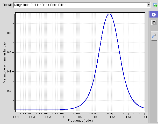
Simulation of first and second order Passive Filter circuits.


Category
Published on
Abstract
Filter circuits are used in a wide variety of electronic products. For example, a common music system consists of a Woofer and Tweeter. The Tweeter gives out a high pitched sound where as the Woofer gives out a low pitched sound. This is accomplished by allowing passage only to certain frequencies of a sound wave. In this study, an interactive educational tool was built to be accessible to the public on NanoHUB, free of charge. This educational tool focuses on passive filter circuits concepts and consists of four basic types of filters: Low Pass filters (allow passage of low frequencies), High Pass filters (allow passage of high frequencies), Band Pass filters (allow passage only to a certain band of frequencies) and Band Reject filters(rejects a certain band of frequencies). The filter circuits are also sub divided into 1st order (consist of only one storage element-an inductor or capacitor), 2nd order (consist of 2 storage elements), 3rd order (consist of 3 storage elements). The user can choose between a capacitive or inductive model within the 1st order circuits. Graphical representations are provided for each type of filter. The magnitude and phase of the transfer function are provided along with a circuit diagram. The output consists of the Magnitude and Phase plots of the transfer function. As a result this user-friendly tool will allow students or other users to alter values of components within a circuit and visually see how the output changes. This tool will enhance their learning experience because of the presence of diagrams and simulations.
Credits
I would like to thank Aung K San ( ECE 202 Instructor ), Daniel Elliot ( ECE 201 instructor ) for their help and feedback while I was working on this tool.
Sponsored by
SURF (Summer Undergraduate Research Fellowships ) , Purdue University
Cite this work
Researchers should cite this work as follows:
-
1. DeCarlo, Raymond A., and Pen-Min Lin. Linear Circuit Analysis: Time Domain, Phasor, and Laplace Transform Approaches. New York: Oxford UP, 2001. Print.
2. "Filter Circuits." Hyper Physics. N.p., n.d. Web. 25 July 2012.