Spin-Circuit Model: Non-Local Graphene Spin-Valve
In this page, we describe how the existing modules can be used to model a 4-magnet graphene spin-valve experiment [1] that quantitatively captures the observed non-local voltage "steps" observed in the experiment while the individual magnets are being flipped by a globally applied magnetic field. The usual non-local spin-valve with 2-magnets [2] is theoretically benchmarked using our modules and is known to reproduce the Takahashi-Maekawa model exactly. The purpose of this example is to show how the Modular Approach [3] can go beyond the known theoretical problem using a straightforward extension of the setup.
In the actual experiment, the in-plane magnets have different thicknesses and therefore varying coercivities, and they switch one after the other as the magnetic field is ramped from zero to a higher value. The spin-circuit approach that combines transport equations with magnetization dynamics of the magnets allow the numerical experiment to be carried out similarly to the experiment: A magnetic field is ramped up very slowly in the spin-circuit, which is globally applied to each ferromagnet with different coercivities so that they flip one after the other, just as in the experiment.
Going beyond the 2-Magnet Non-Local Spin-Valve
The spin circuit model of the structure can be assembled using the Non-Magnet module that is based on diffusive transport for Graphene, with the appropriate sheet conductivity and spin-flip length measured and extracted from the experiment, the Ferromagnet, and the FM||NM Interface modules, coupled with LLG solvers to model the magnetization dynamics as shown below.
The sheet conductivity of graphene is a function of the gate voltage applied, through a back gate in this experiment, and can be modeled to be voltage dependent within the NM module for the circuit simulator. However, we assumed the gate voltage to be a constant in this version and used the Graphene sheet conductivity for a back-gate voltage of -40 V, which is 0.5 kOhms/sq which was extrapolated from the measured conductance dependence of the Graphene in the actual experiment.
Physical Structure |
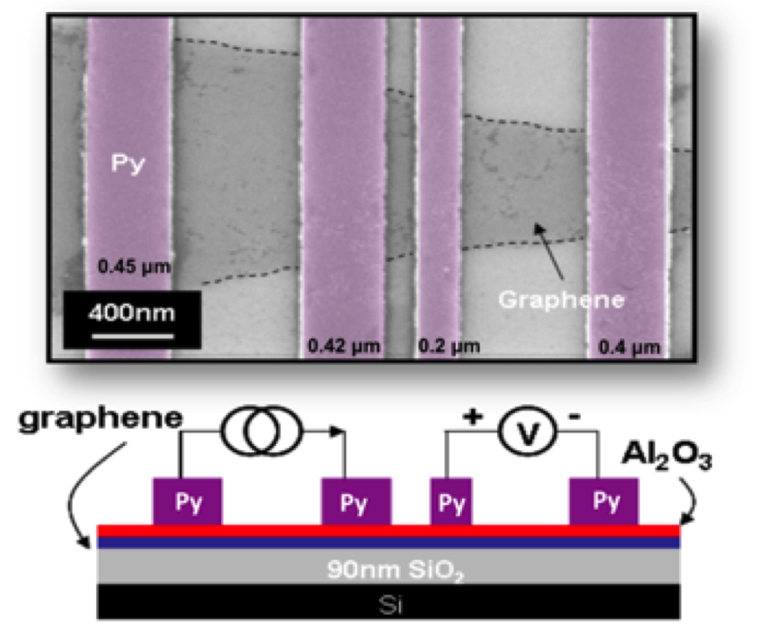 |
Spin-Circuit Model |
|

Similar to the classic non-local spin valve example, where there are at least two magnets [Ref:Takahashi-Maekawa] in the structure, the spin-current injection from a magnet to the channel is controlled by a tunneling barrier captured by the FM||NM Interface module in our framework specified by a tunneling polarization factor, in addition to the bulk ferromagnetic regions that are specified by a bulk polarization, bulk conductivity and bulk spin-flip lengths.
Note that we also use this interface module when dealing with spin-driven nanomagnets, however the spin-torque driven process involves the non-collinear spin-components, and in this experiment only the collinear portion of the interface (top 2x2, which involves polarization and conductance) changes the results.
Spin-Circuit vs Experiment
Experiment |
Spin-Circuit |
|
Non-Local Resistance |
 |
 |
There are several things to note about the quantitative comparison between the experiment and the spin-circuit:
- Asymmetry in the experiment : The experiment shows an asymmetry in measured resistance between the positive and negative sweep of the magnetic field. Theoretically the extra step is clearly observed and the sweeps result in symmetric non-local resistance.
- Measured background signal : In the experiment the non-local resistance sits on a background signal, which is not the same as what we obtained from the spin-circuit even when using the measured parameters as much as we could. The background signal in the experiment likely depends on factors that are not captured by the circuit, but note that there is a background signal predicted in the spin-circuit and in principle this value could be matched to experiment with a judicious choice of parameters. We did not make such an attempt in this example.
- Quantitative values of the steps : Even though the background signal is not matching the experiment, the quantitative steps due to the switching of nanomagnets seem to be very close to the experimentally measured values. There are no free parameters in the spin-circuit, other than using the measured contact resistances, polarizations, and the extracted spin-flip length from the experiment.
Download
The code package with detailed numerical parameters that are used to generate the plots in this page is available here.
A sample waveform is attached in the code package to analyze the data. HSPICE-2013 was used in our circuit simulations.
A MATLAB file that makes use of the HSPICE Toolbox for MATLAB is attached for easy retrieval of the data.
Questions/Comments
Please contact kcamsari-purdue-dot-edu for questions or comments regarding this page.
References
[1] Gao, Yunfei, et al. "Optimized spin relaxation length in few layer graphene at room temperature." 2012 International Electron Devices Meeting. 2012.
[2] Takahashi, S., and S. Maekawa. "Spin injection and detection in magnetic nanostructures." Physical Review B 67.5 (2003): 052409.
[3] Camsari, Kerem Yunus, Samiran Ganguly, and Supriyo Datta. "Modular Approach to Spintronics." Scientific reports 5 (2015).