nanoHUB IGNITE 2021

Nanophotonics Challenge
Instructions
Our eyes perceive what reflects towards us. Many colors in nature are due to pigments, but many are not. Have you ever wondered why soap bubbles are colorful, although the bubble wall itself is transparent? This is due to light-matter interactions. In fact, thin films create light interference effects that change reflected colors due to small changes in the physical thickness of the film.
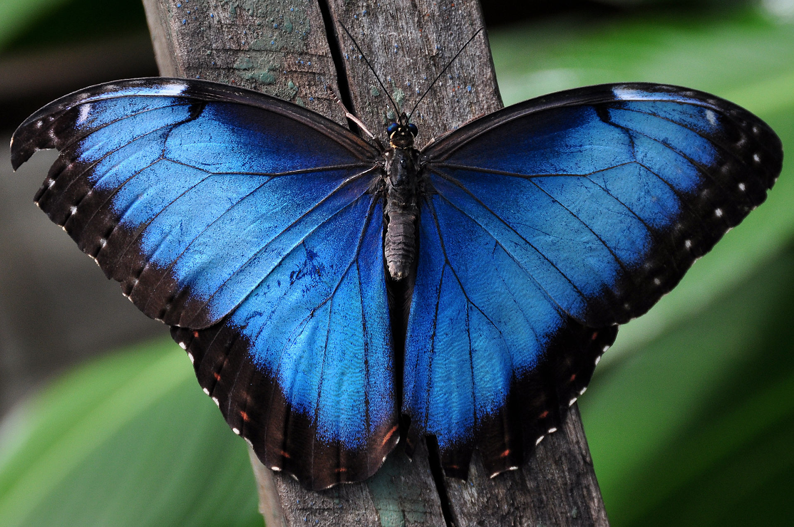
The blue morpho butterfly is a wonderful example of interference and diffraction effects. The iridescent blue color you see is what we call "structural color". The wings of the blue morpho butterfly are not pigmented. Rather, layers of nanostructures on the surface of the blue morpho butterfly create diffraction and interference effects that give strong reflection of blue wavelengths of light.
Figure 1: A Morpho menelaus while resting.
https://commons.wikimedia.org/wiki/File:Blue_Morpho.jpg
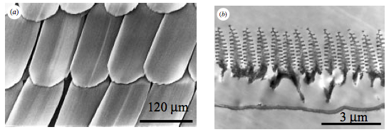
Scientists have studied the details of this butterfly wing. SEM images have shown micrograting structures that look like Christmas trees ( Fig. 2). These structures inspired scientists to mimic this effect by creating similar micrograting structures to produce tunable optical surfaces.
Figure 2: SEM images of the wing of an M. rhetenor butterfly [2].
The Challenge
Visible light is in the wavelength band between 400 and 700 nm in the electromagnetic radiation spectrum. Wave optics is the study of light as a traveling wave that consists of inter-related time-varying electric and magnetic fields. The mathematical representation of wave optics is encapsulated in Maxwell’s equations, which incorporate many previously observed laws in electricity and magnetism such as Ampere’s law and Faraday’s law.
Light waves behave differently depending on the medium they travel in. For example, the wavelength of an optical wave changes in different media. When an optical wave hits a new structure, material or interface, its properties drastically change. Our morpho butterfly is a great example of this. In fact, many observable optical phenomena such as reflection, refraction, diffraction, and interference [4,5] are well described in wave optics.
Solving Maxwell’s equations in complicated structures and at the interfaces is not an easy task if done analytically. Nonetheless, the power of computational techniques made this task accessible for optical designers everywhere. Nowadays, optical or EM simulations are the go to in many industries and for researchers to expect the behavior of many engineered devices.
Electromagnetic (EM) simulations have enabled unprecedented capabilities in designing microstructures with light wavelength tuning, flat optics, or optical beam steering effects, to name a few applications. Many of these microstructures were inspired by tiny periodic structures available in nature, like our example here.
In this challenge, we would like to use open-source EM simulation tools available on nanoHUB.org to mimic the blue morpho microstructure. The tool we’ll use is called Stanford Stratified Structure Solver (S4). This EM tool is a frequency domain code to solve the linear Maxwell’s equations in layered periodic structures. Internally, it uses a computational technique called “Rigorous Coupled Wave Analysis” or RCWA; also called the Fourier Modal Method (FMM) and the S-matrix algorithm [6].
Based on our understanding of the structural coloring of the blue morpho butterfly, we would like to simulate a similar structure to understand the reflection spectrum and tune this optical effect. The Christmas-tree structure shown in Fig. 3 is simulated and fabricated in [3]. Other useful references are also cited below [2, 7].
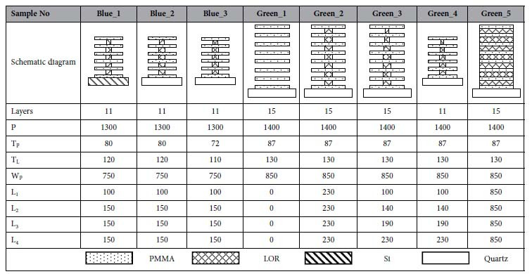
Many structures have been tested in [3]. Details of the simulated and fabricated structures are summarized in Table I.
Figure 3: Schematic diagram for the Morpho butterfly wing scales as depicted in [3]. (a) The original configuration similar to real wing scales with Christmas-tree shape and off-set lamellar layers. (b) The designed scales to be fabricated with aligned lamellar structures of PMMA/LOR in alternate layers. (c) Definitions of dimension symbols used in the text.
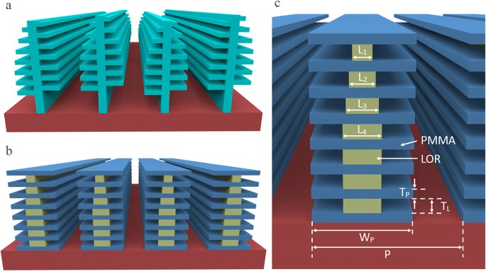
Table I: The sample names and the corresponding schematic diagrams of the designed and fabricated lamellae layers on artificial wing scales are all listed in the table. The dimensions of the ridge grating period (P), layer thickness (T), branch widths (W) and pillar width (L) are all in nanometers. Refractive indices of PMMA, LOR and Quartz are 1.5, 1.58, and 1.544, respectively.
Navigating the problem
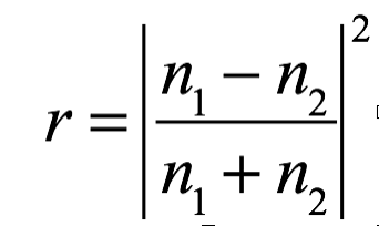
- Start with a simple semi-infinite layer made of Quartz. Test normal incidence reflection spectra over the optical wavelength range (400 nm - 700 nm). Check your results against the Fresnel reflection formula that describes the reflection coefficient between two different media at normal incidence:
- Now let’s add more features to obtain more interesting spectra. Include multilayers to your structure to build the sample labeled as Green_1. What do you notice in your spectra? What do you think causes this selective spectral response in your results?
-
The structure built in Green_1 cannot be fabricated without supporting layers in between. The samples labeled as Green_2 and Green_3 are simple Christmas tree-like structures. Compare your results obtained from each sample to your results obtained from Green_1. Why do you think these samples are labeled as Green_?
-
A useful analysis to understand the effect of multilayer interference is to make a simple micrograting structure without the tree-like features. Sample Green_5 is a good example to test. Comparing the reflection spectra of Green_5 to all the previous results, how do you understand the structural coloring phenomenon of the blue-morpho butterfly?
Innovation
-
Use S4 to similarly compute reflection spectra of all the samples labeled as Blue_
-
Increase the number of alternating layers from 11 to 15 for Blue, and from 15 to 19 for Green. Comment on any possible changes of the reflection spectra.
-
How would you tune the structural parameters to tune the reflection spectra?
-
Choose one of the tree-like structures and test their maximum-intensity wavelength dependence on the incident angle.
Include in your technical submission:
-
Lua Simulation files
-
Simulation results matching reference [3] and interpretations based on questions 1-4 (Navigating the problem).
-
Simulation results for any question in the innovation list.
Reference Papers and Links
[1] YouTube Video: What Gives the Morpho Butterfly Its Magnificent Blue? | Deep Look
[2] Vukusic, P., et al. Quantified interference and diffraction in single Morpho butterfly scales. Proceedings of the Royal Society of London. Series B: Biological Sciences 266.1427 (1999): 1403-1411.https://doi.org/10.1098/rspb.1999.0794
[3] Zhang, S., Chen, Y. Nanofabrication and coloration study of artificial Morpho butterfly wings with aligned lamellae layers. Sci Rep 5, 16637 (2015). https://doi.org/10.1038/srep16637
[4] Ellingson, Steven. Electromagnetics Volume 1 (beta). Virginia Tech Libraries, 2018.https://open.umn.edu/opentextbooks/textbooks/532
[5] Joannopoulos, John D., et al. "Molding the flow of light." Princeton Univ. Press, Princeton, NJ [ua] (2008). http://jdj.mit.edu/book/
[6] Liu, V., and Fan, S., S4: A free electromagnetic solver for layered periodic structures. Computer Physics Communications 183, 2233-2244 (2012)http://dx.doi.org/10.1016/j.cpc.2012.04.026
[7] England, G., et al. Bioinspired micrograting arrays mimicking the reverse color diffraction elements evolved by the butterfly Pierella luna. PNAS November 4, 2014 111 (44) 15630-15634; first published October 6, 2014; https://doi.org/10.1073/pnas.1412240111
nanoHUB Resources
-
S4: Stanford Stratified Structure Solver
https://nanohub.org/tools/s4sim -
S4Sim Documentation
https://web.stanford.edu/group/fan/S4/
nanoHUB IGNITE 2021 is sponsored in part by: